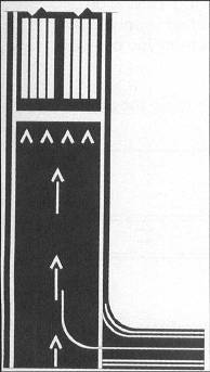
Each feeder route will terminate at the TAA boundary and will be aligned along a path pointing to the associated IAF. Check out the full series. However, if no such note is published, and for simultaneous independent approaches (4300 and greater runway separation) where an AAUP is not published, pilots are cautioned to monitor their descent on the glide-slope/path outside of the PFAF to ensure compliance with published crossing restrictions during simultaneous operations, When parallel approach courses are less than 2500 feet apart and reduced in-trail spacing is authorized for simultaneous dependent operations, a chart note will indicate that simultaneous operations require use of vertical guidance and that the pilot should maintain last assigned altitude until established on glide slope. How To Land With An Asymmetric Flap Failure, 7 Factors Every Pilot Should Consider Before Flying Around Thunderstorms, How To Fly An Approach To Landing Through Turbulence, Solo Endorsements: Understanding Basic Solo Requirements, Solo Endorsements: Understanding Solo Cross-Country Requirements, The Difference Between Decision Altitude (DA) and Decision Height (DH). VREF, VSO, and the maximum certified landing weight are those values as established for the aircraft by the certification authority of the country of registry. Use of icons is necessary to avoid obscuring any portion of the "T" procedure (altitudes, courses, minimum altitudes, etc.). Operational approval must also be obtained for Baro-VNAV systems to operate to the LNAV/VNAV minimums. A new type of nonprecision WAAS minima will also be published on this chart and titled LP (localizer performance). Quiz: Do You Know These 6 Light Gun Signals? If a pilot chooses to operate at a higher speed, other factors should be modified to ensure that the aircraft remains within the circling approach protected area, Wind speed and direction. Instrument Approach Procedures, or IAPs for short, are established to provide the transition from the en-route structure to the terminal environment when operating under Instrument Flight Rules (IFR), and/or during Instrument Meteorological Conditions (IMC), to a point where a safe landing can be made, Simply stated, they are "road" maps for the sky for the terminal area, Once approved, instrument approach procedures are published and distributed by the government and commercial cartographers as, While headings and altitudes will change, approaches generally follow the same rules, Charts consist of five principal sections: [, The pilot briefing and procedure notes are the starting place for any approach to be flown, and are directly related to the conduct of the. If the pilot is not familiar with the specific approach procedure, ATC should be advised and they will provide detailed information on the execution of the procedure, When operating in accordance with an IFR clearance and ATC approves a change to the advisory frequency, make an expeditious change to the CTAF and employ the recommended traffic advisory procedures, Whenever possible, the CTAF will be used to control airport lighting systems at airports without operating control towers. If uncertain of the meaning of the clearance, immediately request clarification from ATC, An aircraft is not established on an approach while below published approach altitudes. Obstacle clearance is provided to allow a momentary descent below DA while transitioning from the final approach to the missed approach. NPA without FAF. Quiz: Can You Answer These 6 IFR Regs Questions? A published VDA on these procedures does not imply that landing straight ahead is recommended or even possible. As NDBs are decommissioned, their use during instrument approach procedures is becoming more and more uncommon. Up to four lines of minima are included on these charts. Further guidance may be found in Advisory Circular 90-105, Aircraft approach category means a grouping of aircraft based on a speed of VREF at the maximum certified landing weight, if specified, or if VREF is not specified, 1.3 VSO at the maximum certified landing weight. It is similar to the ILS ident, but displayed visually rather than aurally. Still looking for something? This includes Class 3 and 4 TSO-C146 GPS/WAAS equipment, LNAV/VNAV identifies APV minimums developed to accommodate an RNAV IAP with vertical guidance, usually provided by approach certified Baro-VNAV, but with lateral and vertical integrity limits larger than a precision approach or LPV. It is not a function of procedure design to ensure compliance with FAR 91.175. A VDP may not be published under certain circumstances which may result in a destabilized descent between the MDA and the runway touchdown point. The CTAF is published on the instrument approach chart and in other appropriate aeronautical information publications. Many of these outages will be very short in duration, but may result in the disruption of the vertical portion of the approach. For simultaneous close parallel (PRM) approaches, the Attention All Users Page (AAUP) may publish a note which indicates that descending on the glide-slope/glidepath meets all crossing restrictions. LP will only be published if terrain, obstructions, or some other reason prevent publishing a vertically guided procedure. Identified obstacle penetrations may cause restrictions to instrument approach operations which may include an increased approach visibility requirement, not publishing a VDP, and/or prohibiting night instrument operations to the runway. A chart note will be published in the pilot briefing strip "Procedure NA at Night" [, Use of a VGSI may be approved in lieu of obstruction lighting to restore night instrument operations to the runway. Before initiating an IAP that contains a "Fly Visual to Airport" segment, the pilot should have pre-planned climb out options based on aircraft performance and terrain features. Pilots should be aware that excessive bank angle can lead to a loss of aircraft control, Indicated airspeed. After the aircraft is so established, published altitudes apply to descent within each succeeding route or approach segment unless a different altitude is assigned by ATC. Pilots must be aware that the published VDA is for advisory information only and not to be considered instrument procedure derived vertical guidance. Barometric altimeter information remains the primary altitude reference for complying with any altitude restrictions. The IAF for each area of the TAA is included on the icon where it appears on the approach to help the pilot orient the icon to the approach procedure. Accordingly, pilots are advised to carefully review approach procedures to identify where the optimum stabilized descent to landing can be initiated. The VDA and TCH information are charted on the profile view of the IAP following the fix (FAF/stepdown) used to compute the VDA. This speed, at the maximum certificated landing weight, determines the lowest applicable approach category for all approaches regardless of actual landing weight, Precision approaches (PAs) are instrument approaches based on a navigation system that provides course and glidepath deviation information meeting the precision standards of ICAO Annex 10, Examples include: PAR, ILS, and GLS approaches, Approaches with vertical guidance (APVs) are instrument approaches based on a navigation system that is not required to meet the precision approach standards of ICAO Annex 10 but provides course and glidepath deviation information, This means vertical guidance is just that, guidance, and therefore not a precision approach, A non-precision approach (NPA) is an instrument approach based on a navigation system which provides course deviation information, but no glidepath deviation information, Examples include: VOR, NDB and LNAV approaches, Some approach procedures may provide a Vertical Descent Angle as an aid in flying a stabilized approach, without requiring its use in order to fly the procedure, While a VDA may be provided, the approach is designed without requiring its use and so this does not make the approach an APV procedure, since it must still be flown to an MDA and has not been evaluated with a glide-path, The airport diagram provides a general picture of the airfield and will give you some orientation as to what to expect when you break out of the weather, The diagram is not overly specific and many airports have a separate diagram published with the approach plates following all of the procedures, The Terminal Arrival Area (TAA) provides a transition from the en-route structure to the terminal environment with little required pilot/air traffic control interface for aircraft equipped with Area Navigation (RNAV) systems, A TAA provides minimum altitudes with standard obstacle clearance when operating within the TAA boundaries, TAAs are primarily used on RNAV approaches but may be used on an ILS approach when RNAV is the sole means for navigation to the IF; however, they are not normally used in areas of heavy concentration of air traffic, The basic design of the RNAV procedure underlying the TAA is normally the "T" design (also called the "Basic T"), The "T" design incorporates two IAFs plus a dual purpose IF/IAF that functions as both an intermediate fix and an initial approach fix, The T configuration continues from the IF/IAF to the final approach fix (FAF) and then to the missed approach point (MAP), The two base leg IAFs are typically aligned in a straight-line perpendicular to the intermediate course connecting at the IF/IAF, A Hold-in-Lieu-of Procedure Turn (HILPT) is anchored at the IF/IAF and depicted on U.S. Government publications using the "hold-in-lieu -of-PT" holding pattern symbol, When the HILPT is necessary for course alignment and/or descent, the dual purpose IF/IAF serves as an IAF during the entry into the pattern, Following entry into the HILPT pattern and when flying a route or sector labeled "NoPT," the dual-purpose fix serves as an IF, marking the beginning of the Intermediate Segment [, The standard TAA based on the "T" design consists of three areas defined by the Initial Approach Fix (IAF) legs and the intermediate segment course beginning at the IF/IAF, These areas are called the straight-in, left-base, and right-base areas [, TAA area lateral boundaries are identified by magnetic courses TO the IF/IAF, The straight-in area can be further divided into pie- shaped sectors with the boundaries identified by magnetic courses TO the (IF/ IAF), and may contain stepdown sections defined by arcs based on RNAV distances from the IF/IAF [, The right/left-base areas can only be subdivided using arcs based on RNAV distances from the IAFs for those areas, Entry from the terminal area onto the procedure is normally accomplished via a no procedure turn (NoPT) routing or via a course reversal maneuver, The published procedure will be annotated "NoPT" to indicate when the course reversal is not authorized when flying within a particular TAA sector, Otherwise, the pilot is expected to execute the course reversal under the provisions of 14 CFR Section 91.175, The pilot may elect to use the course reversal pattern when it is not required by the procedure, but must receive clearance from air traffic control before beginning the procedure, ATC should not clear an aircraft to the left base leg or right base leg IAF within a TAA at an intercept angle exceeding 90.
When a depicted altitude is specified in the ATC clearance, that altitude becomes mandatory as defined above, The ILS glide slope is intended to be intercepted at the published glide slope intercept altitude. The RNAV chart includes information formatted for quick reference by the pilot or flight crew at the top of the chart. For this purpose, the procedure turn of a published IAP must not be considered a segment of that IAP until the aircraft reaches the initial fix or navigation facility upon which the procedure turn is predicated, Cross Redding VOR at or above five thousand, cleared VOR runway three four approach. When a time to leave the holding point has been received, the pilot should adjust the flight path to leave the fix as closely as possible to the designated time, "Free Digital Products" on left side of page, "View Terminal Procedures Publications (d-TPP) and Airport Diagrams" in box on right side of page, "digital - Terminal Procedures (XXXX)" is the link in the middle center of the page, Now all the approaches for that airport will be brought up, In the "Flag" column any approach that was "A" added, "D" deleted, or "C" changed since the last publication cycle will be "flagged", Be aware that controller issues clearance for approach based only on known traffic. It is possible to have LP and LNAV published on the same approach chart but LP will only be published if it provides lower minima than an LNAV line of minima. Angular guidance does not refer to a glideslope angle but rather to the increased lateral sensitivity as the aircraft gets closer to the runway, similar to localizer approaches. Runway Light Colors And Light Spacing, Explained. Pilots should descend to the TAA altitude after crossing the TAA boundary and cleared for the approach by ATC [, Each waypoint on the "T" is assigned a pronounceable 5-letter name, except the missed approach waypoint.

In addition, the pilot must be authorized by the FAA to fly special instrument approach procedures associated with private navigation aids (see paragraph 5-4-8). The RNAV IAP format includes the descent angle to the hundredth of a degree; e.g., 3.00 degrees. When receiving IFR services, the pilot/aircraft operator is responsible for determining if weather/visibility is adequate for approach/landing, When making an IFR approach to an airport not served by a tower or FSS, after ATC advises "CHANGE TO ADVISORY FREQUENCY APPROVED" you should broadcast your intentions, including the type of approach being executed, your position, and when over the final approach fix inbound (nonprecision approach) or when over the outer marker or fix used in lieu of the outer marker inbound (precision approach).